


Here’s a question that trips up even experienced installers: you’ve wired the SLC loop perfectly, every detector is addressed, and the panel passes every diagnostic. Then inspection day comes, and the whole job gets flagged because a strobe in the back office is rated too low for the room it’s covering.
Detection gets most of the attention in fire alarm design, but notification is just as strictly regulated, and the rules around it are more specific than most people expect. This guide breaks down how notification appliance circuits work, what separates a horn from a strobe from a combo unit, and how candela ratings actually get calculated so your next fire alarm system installation doesn’t stall at inspection.
What Is a Notification Appliance Circuit (NAC)?
A NAC is the circuit that powers the devices telling people to evacuate: horns, strobes, and combination horn/strobe units. It’s wired separately from the SLC loop that handles detection, which we covered in our full addressable wiring diagram guide.
That separation matters. Detection and notification serve different jobs, and mixing them onto the same circuit creates both a code violation and a practical headache when troubleshooting a fault. If you’ve seen our earlier wiring diagram, the NAC circuit is the branch running from the panel out to the horn/strobe devices, independent of the SLC loop entirely.
The Three Types of Notification Appliances
Audible Appliances (Horns)
Horns produce a standardized temporal pattern, three short pulses followed by a pause, repeated continuously. This pattern, known as Temporal-3 or T3, is the same across virtually all modern systems so occupants recognize it instantly regardless of building.
Horns are required in any space where someone might not be looking at a strobe when an alarm activates.
Visual Appliances (Strobes)
Strobes exist for occupants who can’t rely on sound alone, whether due to hearing loss or a noisy environment like a mechanical room or industrial floor. They flash at a synchronized rate of 1 Hz and are now required in most commercial spaces under both NFPA 72 and ADA accessibility guidelines.
Strobe brightness is measured in candela (cd), and that number isn’t arbitrary. It’s calculated based on room size, mounting location, and ceiling height, which we’ll break down below.
Combination Horn/Strobe Units
This is the device you’ll see most often on a real job site. Rather than running separate horn and strobe circuits, a combination unit handles both functions from a single appliance, simplifying wiring and reducing the number of devices needed per room.
In systems using voice evacuation, speaker/strobe combinations replace the horn entirely, allowing live or pre-recorded voice instructions instead of a standard tone.
How Candela Ratings Actually Work
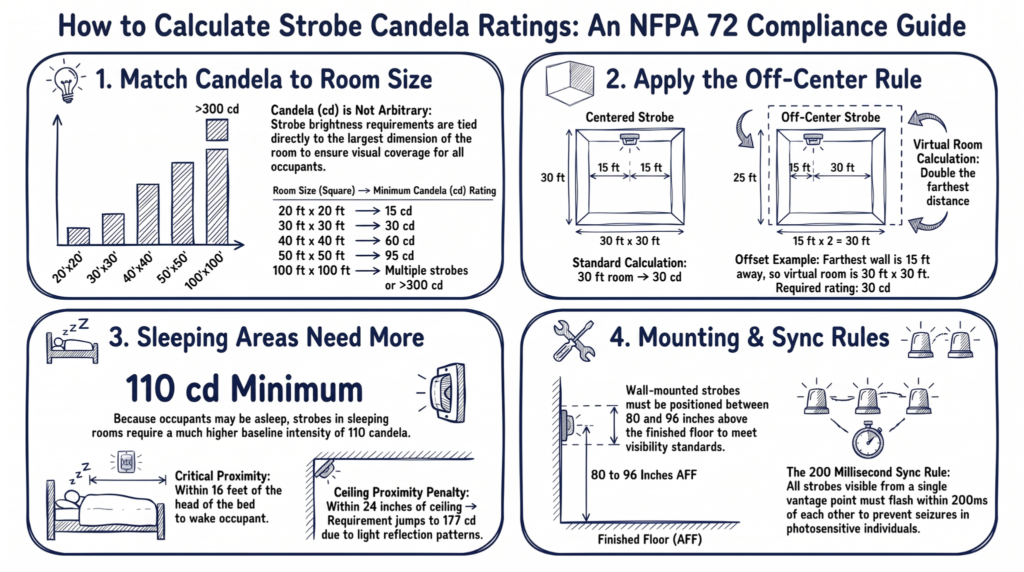
This is where most installation mistakes happen. NFPA 72 doesn’t let you pick a strobe candela rating based on guesswork. It’s tied directly to the size of the room and where the strobe is mounted.
For wall-mounted strobes, the code provides a table based on the room’s largest dimension:
- 20 ft × 20 ft room: 15 cd minimum
- 30 ft × 30 ft room: 30 cd
- 40 ft × 40 ft room: 60 cd
- 50 ft × 50 ft room: 95 cd
- 100 ft × 100 ft room: multiple strobes, or a single high-output unit rated well above 300 cd
Ceiling-mounted strobes use a separate table that factors in ceiling height alongside room size, since a strobe mounted higher needs more output to deliver the same effective intensity at floor level.
A Detail Most Guides Skip: Off-Center Placement
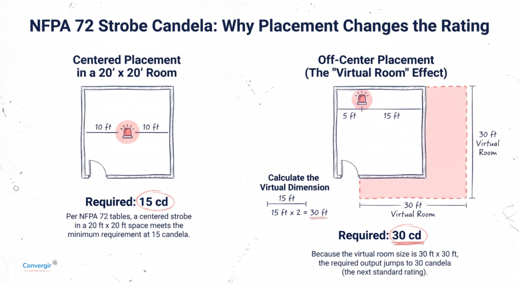
If a strobe isn’t mounted at the center of a wall, the required candela rating changes. The code treats the strobe as sitting in the middle of a “virtual room,” so if it’s offset five feet from one wall in a 20-foot-wide space, you measure to the farthest wall, double that distance, and select candela based on that larger virtual dimension. In that example, a strobe that would only need 15 cd if centered actually needs closer to 34 cd once you account for the offset.
Skipping this calculation is one of the most common reasons strobe placement fails plan review.
Sleeping Areas Have Their Own Rules
Hotels, dormitories, and residential care facilities carry stricter requirements, since occupants may be asleep when an alarm activates.
- Strobes in sleeping rooms require a minimum of 110 cd
- The strobe must be located within 16 feet of the head of the bed
- If mounted within 24 inches of the ceiling, the required rating jumps to 177 cd
- Not every room in a large hotel needs a strobe; NFPA 72 sets a percentage based on total room count, starting around one in every 25 rooms for smaller properties
Sleeping areas may also require supplemental devices like bed shakers for occupants who need tactile notification in addition to visual and audible signals.
Mounting Height and Synchronization Rules
A correctly rated strobe installed at the wrong height still fails inspection. NFPA 72 requires:
- Wall-mounted strobes positioned between 80 and 96 inches above finished floor
- Ceiling-mounted strobes permitted only where ceiling height doesn’t exceed 30 feet
- Any strobes visible from the same vantage point synchronized to flash within 200 milliseconds of each other
That last rule isn’t just a preference. Unsynchronized strobes flashing at different intervals in the same field of view can trigger seizures in photosensitive individuals, which is why synchronization modules are standard in modern NAC circuit design.
Designing a NAC Circuit That Passes Inspection the First Time
A few habits consistently separate a smooth notification design from a callback-heavy one:
- Map candela ratings room by room before ordering devices, not after
- Account for off-center mounting in your calculations, not just raw room dimensions
- Confirm total current draw against your NAC circuit’s rated capacity; horns and strobes pull real amperage, and overloading a circuit is a common design error
- Use synchronized devices from the same product line to avoid mismatched flash timing
- Double-check sleeping area requirements separately; they’re easy to overlook on mixed-use buildings
Bringing It Back to the Full System
Notification only works if it’s wired correctly downstream of a properly designed SLC loop and control panel. If you haven’t seen how the NAC circuit fits into the bigger picture, check out our complete addressable fire alarm system wiring diagram guide for a full breakdown of how the panel, detectors, modules, and notification circuit all connect, with a labeled diagram showing exactly where NAC wiring branches off from the rest of the system.
Getting candela ratings and NAC design right isn’t just about passing inspection. It’s about making sure every occupant, hearing or not, sleeping or awake, gets the warning they need when it counts.
