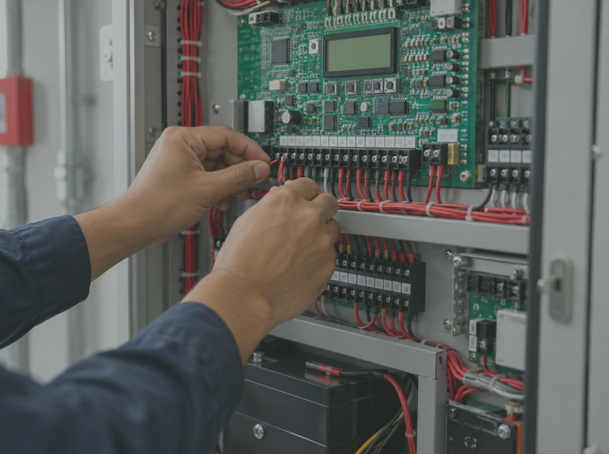
Imagine a fire panel that doesn’t just flash “zone 2” and leave you guessing. It tells you “smoke detector, room 214, north stairwell,” pointing you straight to the spot in seconds. That’s the kind of precision a well-wired system delivers, and it’s a game changer for how quickly a building can respond.
That level of precision is the whole point of an addressable fire alarm system, and it only works if the wiring behind it is done correctly. This guide breaks down exactly how that wiring comes together, with a diagram you can follow step by step, whether you’re an installer, an engineer, a student, or a facility manager trying to understand what’s behind the panel.
Addressable vs. Conventional: Why the Wiring Matters
Before getting into wiring specifics, it helps to know what problem addressable technology actually solves.
Conventional fire alarm systems wire groups of detectors into zones. When something trips, the panel can only tell you which zone, not which device. In a large building, that zone might cover dozens of rooms.
Addressable systems solve this by giving every device on the loop, detectors, modules, pull stations, its own digital address. The panel polls each one individually and knows exactly which device changed state. That’s why addressable fire alarm systems have become the default choice for:
- Office buildings and commercial complexes
- Hospitals and senior care facilities
- Hotels and multi-tenant residential buildings
- University campuses and large industrial sites
Smaller, single-zone buildings can often get by with conventional wiring. Anything larger or more complex benefits from the precision addressable wiring provides.
The Core Idea Behind SLC Loop Wiring
At the heart of every addressable fire alarm system installation is the SLC loop, short for signaling line circuit. This is the wiring backbone that carries both power and digital communication to every device on the system.
Instead of running a separate pair of wires to each detector like a conventional system does, the SLC loop connects multiple devices in sequence along a shared circuit. The panel continuously polls each address on the loop, checking whether that device is reporting normal, alarm, or trouble status.
This single design choice is what gives addressable systems their two biggest advantages: precise location reporting and dramatically simpler troubleshooting.
What You’re Actually Wiring: Core Components
Before you pull a single wire, it pays to know exactly what’s going on the loop. A standard addressable installation includes:
- Fire Alarm Control Panel (FACP): the central processing unit, backed by a dedicated power supply and battery
- SLC loop: wired in either Class A or Class B, depending on the level of redundancy required
- Addressable detectors: smoke and heat detectors, each assigned a unique address
- Monitor modules: bring conventional inputs (pull stations, flow switches) onto the addressable loop
- Control modules: convert digital commands into outputs, like releasing a door holder or shutting down an air handler
- Isolator modules: contain wiring faults so one short doesn’t disable the whole loop
- NAC circuit: a separate circuit powering horns and strobes
Keep this list in mind as you look at the diagram in the next section. Every one of these pieces has a specific place in the wiring.
Reading the Wiring Diagram
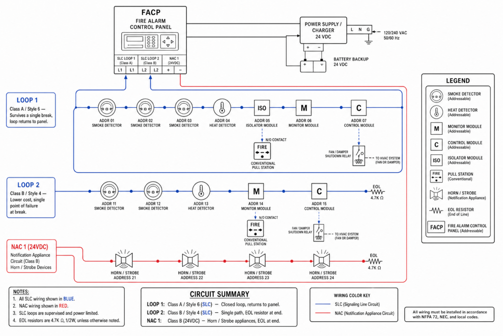
The diagram above lays out a simplified addressable system: a power supply feeding the FACP, an SLC loop wired in Class A through a smoke detector, a monitor module, and a control module, an isolator module positioned near the end of the run, and a separate NAC circuit feeding two notification devices.
A couple of details worth paying attention to:
- The loop leaves the panel, threads through each device, and returns along an independent path. That return path is what defines Class A wiring, and it’s what keeps the loop alive even if one section is damaged.
- The isolator sits between device groups deliberately. If a short happens on one side, the isolator prevents it from taking out devices on the other side.
- Detection and notification are wired as two separate circuits. They never share the same run.
Real-world systems usually have more devices per loop and often multiple loops feeding a single panel, but the underlying wiring principle scales exactly the same way, regardless of building size.
How Each Connection Actually Functions
The SLC loop does double duty, delivering power and carrying digital data to every device in sequence. Device addresses are typically set before installation using rotary switches, a handheld programmer, or panel-based auto-addressing.
Monitor modules act as translators. A conventional pull station or sprinkler flow switch connects to the module, and the module reports that device’s status to the panel using its own address.
Control modules work in reverse, turning a digital command from the panel into a physical action, closing a relay to trigger a door release or elevator recall.
Isolator modules are inexpensive but critical. Positioned strategically along the loop, they detect abnormal resistance from a short and open the circuit on both sides of the fault automatically.
Wiring Rules That Prevent Callbacks
A handful of habits separate a smooth fire alarm system installation from one that needs constant revisits:
- Confirm the panel’s maximum loop resistance and device capacity before finalizing your device count
- Match wire gauge to run length; longer runs need heavier gauge to prevent voltage drop
- Use fire-rated cable as specified by applicable IS standards and local fire safety codes
- Physically separate fire alarm wiring from power wiring runs
- Label every device and cable run to match your as-built drawings
- Track device addresses in a spreadsheet as you assign them to avoid duplicates
If you’re planning a fire alarm system installation in Chennai or reviewing an existing wiring layout, don’t leave it to guesswork
Mistakes That Show Up During Commissioning
Certain errors surface again and again on addressable jobs:
- Reversed polarity on NAC circuits or control module outputs
- Isolator modules skipped entirely or placed in the wrong location
- Loop runs that exceed the panel’s rated resistance limit
- Mixed wire gauges without recalculating voltage drop across the run
- Missing or inconsistent labeling that turns commissioning into detective work
Testing Before You Call It Done
Wiring isn’t finished until it’s verified. Start with a continuity and resistance check across the entire loop, then confirm every device address matches your documented device list.
Simulate a fault to confirm isolator modules actually isolate as designed. Follow with a full functional test, triggering an alarm condition and confirming every notification appliance responds correctly. Document every result. Thorough records are expected both for good practice and for Fire NOC approval from your local fire authority.
Conventional vs. Addressable Wiring at a Glance
| Feature | Conventional | Addressable |
|---|---|---|
| Fault location | Zone level only | Exact device |
| Wiring complexity | Simpler | More involved, more efficient per device |
| Troubleshooting | Manual zone search | Panel identifies exact device |
| Scalability | Limited | Expands easily |
| Best suited for | Small, single-zone buildings | Commercial and multi-story properties |
Wiring It Right the First Time
Every choice in an addressable fire alarm system, from Class A routing to isolator placement, exists for one reason: to give the panel enough information to pinpoint a problem the instant it happens.
Getting the wiring right isn’t just about code compliance. It’s about making sure the system performs exactly when it matters most.
If you’re planning a new fire alarm system installation or reviewing an existing wiring layout, don’t leave it to guesswork. Contact a licensed fire alarm technician or design engineer to review your plan before installation begins. It’s the most reliable way to avoid costly rework and make sure your building is protected from day one.
Frequently Asked Questions
It depends on the panel manufacturer, generally somewhere between 99 and 250+ devices per loop. Always confirm against your specific panel’s spec sheet.
Class A includes a return path to the panel, so the loop stays functional even after a single break. Class B is a simpler, less expensive dead-end run, but everything downstream of a break goes offline. For a full side-by-side comparison, read our Class A vs Class B fire alarm wiring guide.
Yes. A monitor module gives a conventional device its own address on the addressable loop.
Nicked insulation, moisture intrusion, or physical damage during installation are the most common causes.
Start at the far end of the loop and test continuity backward toward the panel until you locate the break.