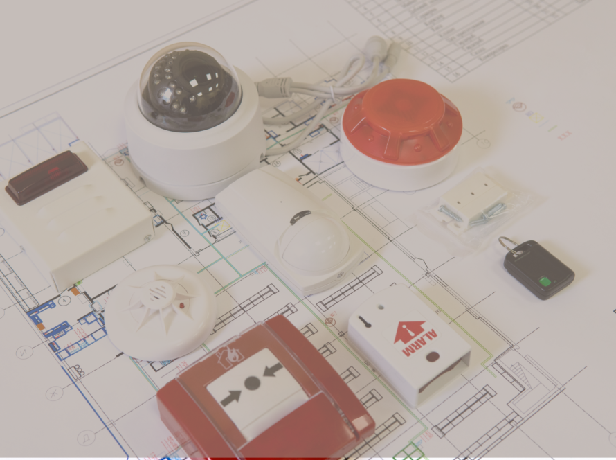
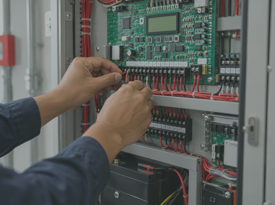
The control panel is the brain of a fire alarm system. Detectors and call points send it signals, and it decides what happens next. A panel that is mounted in the wrong place, wired without checks, or left with default settings can fail at the moment it matters.
This guide walks through how a fire alarm control panel is installed, from the checks before the box goes on the wall to the tests after it powers up. It covers conventional and addressable panels. Always follow the manufacturer’s manual for your specific panel, because terminals, power-up steps, and programming differ between models.
Quick Summary
- Follow the approved drawings for the panel position and the circuit layout.
- Mount the panel in a clean, dry, reachable place on a solid wall.
- Test the field wiring before you power the panel.
- Connect the mains first. Connect the battery at the end of commissioning, following the manufacturer’s sequence.
- Program the labels and the cause-and-effect logic, and change the factory access codes.
- Test every circuit, device, and output, and record the results.
- Leave the panel in normal mode with nothing disabled, and hand over the documents.
Safety First
The panel connects to mains power and a life safety system, so treat the work with care:
- Isolate and lock out the mains supply before anyone works inside the panel. Only trained people should do this work.
- Take electrostatic precautions when you handle circuit boards, because static can damage them.
- Keep metal shavings and dust out of the enclosure. Cover the boards or take them out while you drill or mount the box.
- Never short the battery terminals. A short circuit can cause arcing and fire.
What the Control Panel Does
The panel does four jobs:
- Receives signals. It listens to detectors, manual call points, and other inputs.
- Shows what happened. It displays the alarm, fault, or warning, and where it came from.
- Triggers outputs. It sounds the alarms and can start other actions, such as releasing door holders or signalling other systems.
- Watches itself. It checks its own power, battery, and wiring, and reports faults.
Conventional and Addressable Panels
The two panel types connect to the field devices differently, so the installation work differs too.
- Conventional panels have zone circuits. Each zone connects a group of detectors and call points, and the panel shows which zone is in alarm. Each zone ends with an end-of-line device so the panel can monitor the wiring.
- Addressable panels have signaling line circuit (SLC) loops. Every device on the loop has its own address, so the panel shows exactly which device triggered. Our addressable fire alarm wiring guide shows how a loop connects, and our Class A vs Class B wiring guide explains how the loop layout affects a wire break.
Before You Start
Most installation problems begin before the first screw. Check these first:
- The approved drawings. Confirm the panel location, device count, and circuit layout match the approved design.
- The panel capacity. Check that the panel has enough loops or zones, enough capacity for the planned devices, and enough output current for the alarm circuits.
- The total load. Add up the current drawn by the detection circuits, the alarm circuits, and any auxiliary outputs. Confirm the total stays within the panel’s rating.
- The power supply and battery. Confirm the supply and battery suit the full load. The section on battery sizing below explains how.
- The manufacturer’s manual. Keep the wiring diagram and installation instructions on site.
- The site. The wall should be finished, dry, and clean. Cover the panel during construction work so dust does not get inside.
- The people. Use trained installers, and agree who isolates the mains before work starts.
Fire Alarm Control Panel Wiring and Connections
A typical panel has connections for these things:
- Mains input and the protective earth
- The backup battery
- Detection circuits: zone circuits on a conventional panel, or SLC loops on an addressable panel
- Alarm circuits for sounders and strobes (also called notification circuits)
- Relay outputs, usually for fire and fault signals to other systems
- An auxiliary power output for external devices
- Communication ports for repeater displays, PC programming, and building management links
- Remote inputs, on some models
Terminal names and layouts differ between models, so use the manufacturer’s wiring diagram for your panel. Relay outputs are often not monitored by the panel, so test them and keep their wiring power-limited.
How to Size the Backup Battery
The battery must run the panel through a mains failure and still power the alarms. The method is the same for any panel:
- Take the panel’s standby current, including all connected devices, and multiply it by the standby period in hours.
- Take the alarm current, including all sounders, and multiply it by the alarm period in hours.
- Add the two results.
- Add a margin, because battery capacity falls as batteries age and in heat. Your panel manual states the margin it expects.
- Round up to the next battery size that the panel can charge and hold.
The standby and alarm periods come from your approved design and the requirements that apply to your building. They are not fixed numbers for every site.
Example only, with made-up figures: A panel draws 0.1 A in standby, and the design sets a standby period of 24 hours. That gives 2.4 Ah. The alarms draw 1 A, and the design sets an alarm period of 0.5 hours. That gives 0.5 Ah. The total is 2.9 Ah. A 20 percent margin adds 0.58 Ah, so the target is about 3.5 Ah, and the installer then picks the next battery size that the panel supports. Use your own design values and your own panel manual, not these numbers.
Step-by-Step Installation
1. Choose the location
Follow the position shown on the approved drawings. In general, the panel should sit where staff and responders can reach it easily, in a clean, dry area, with clear space around it and a display that people can read comfortably. Avoid places with heat, moisture, vibration, or heavy dust.
2. Mount the enclosure
Fix the enclosure to a solid wall with anchors that suit the wall material and the weight. Keep it level, and leave the working space the manufacturer recommends so technicians can open the door and reach the terminals. Cover the boards or take them out while you drill, so metal shavings and dust stay out of the enclosure.
3. Bring in the cables
- Bring the cables in through the entries the manufacturer provides.
- Keep fire alarm cables separate from power cables.
- Use fire-rated cable as the design and the applicable standards specify.
- Size each cable for its circuit current and length, so the voltage does not drop too far along the run.
- Do not mix detection circuits and alarm circuits in the same cable, unless the manual allows it.
- Secure the conductors near the terminals, so movement does not loosen or damage them.
- Terminate cable screens, where used, as the manual says.
- Label every cable at the panel end.
4. Connect the earth and check the wiring before power
Connect the protective earth as the manual directs. Then test the field wiring while the panel is still off. Check continuity, check insulation, and look for shorts and earth faults. Clear every earth fault before you go on. One earth fault usually gives a trouble signal, but a second earth fault on the same circuit can disable the circuit or cause a false alarm. Finding a fault now is far easier than finding it after power-up.
5. Connect the detection circuits
- Conventional panel: Terminate each zone circuit at its terminals, observe polarity, and fit the end-of-line device at the last point of each zone.
- Addressable panel: Terminate the SLC loop at the loop terminals. For a Class A loop, connect both the outgoing and return wires. For a Class B circuit, connect the single run. Check the panel’s loop capacity and where the design places short-circuit isolators, and follow both.
6. Connect the alarm circuits and outputs
Connect the alarm circuits for the sounders and strobes. Observe polarity, and fit the end-of-line device where the manual requires it. Terminate any unused monitored output as the manual says, because an open output usually makes the panel report a fault. Then connect any relay or monitored outputs, such as door holders or links to other systems, exactly as the design shows.
7. Connect the mains power
Connect the mains supply on its own dedicated circuit. Label it clearly and protect it against being switched off by accident. Switch on the mains and let the panel start up. Do not connect the battery yet. Many manufacturers advise fitting it at the end of commissioning, so you can cut power quickly if something goes wrong. Follow your panel’s manual for the exact order.
8. Program the panel
Set up the panel for the building:
- Assign or auto-learn the device addresses on an addressable system
- Enter clear labels for every device and zone, such as “Second Floor, East Corridor”
- Set the cause-and-effect logic, which defines what each alarm triggers
- Set the date, time, and any delays or verification settings that the design specifies
- Change the factory access codes, and record the new codes with the building owner
Do not leave the panel on its default settings.
9. Test the circuits and devices
Use the test method in your panel’s manual. This table shows what installers typically check:
| Test | What you do | What the panel should show |
|---|---|---|
| Panel check | Hold the lamp test control | All indicators and the display light up |
| Open-circuit test | Disconnect one conductor at the terminals of a monitored circuit | A circuit fault within a few seconds, with no individual device faults |
| Short-circuit test | With the circuit idle, link its two conductors as the manual describes | A circuit fault |
| Device test | Operate every detector and call point | The correct alarm and the correct label on the display |
| Alarm output test | Operate the alarm circuits | Every sounder and strobe works, and the alarm is audible in every area, including stairwells |
| Cause-and-effect test | Trigger each programmed action | Each output does what the design says |
After each test, restore the wiring and reset the panel to clear the fault.
10. Connect the battery and test the backup power
- Check the voltage at the battery terminals against the value in the manual before you connect.
- Connect the batteries, and fit the link between them last. Never short the terminals.
- Test the battery monitoring. Disconnect the link, confirm the panel reports a battery fault, then reconnect it and reset.
- Test a mains failure. Switch off the mains, confirm the panel reports a supply fault and keeps running on the battery, then restore the mains and reset.
11. Final check, documents, and handover
- Reset the panel and confirm it is in normal operating mode, with no disabled zones or devices, no test mode, and no faults.
- Check that the date and time are still correct after the power tests.
- Give the owner the as-built drawings, the device list with addresses, the test records, the panel settings, and the manufacturer’s manuals.
- Show the building staff how to read the display, silence an alarm, and reset the panel.
Common Mistakes During Panel Installation
- Mounting the panel in a hot, damp, or hard-to-reach spot
- Powering the panel before checking the field wiring
- Leaving an earth fault uncleared
- Forgetting the end-of-line devices, or fitting them in the wrong place
- Reversing polarity on circuits
- Running detection and alarm circuits in the same cable
- Leaving conductors unsecured at the terminals
- Using a battery that is too small for the load
- Leaving zones or devices disabled, or leaving the panel in test mode, after commissioning
- Leaving the factory access codes in place
- Labeling devices poorly, so the panel’s messages do not help anyone
- Skipping the documentation
Installing in Chennai: Conditions and Requirements
Chennai is hot and humid, and coastal air can speed up corrosion. Mains supply can also fluctuate, and power cuts happen. These conditions affect panel installation in a few ways:
- Choose a location within the manufacturer’s temperature and humidity range, and keep the enclosure sealed against moisture and dust.
- Check the earthing carefully, and add surge protection where the design calls for it.
- Confirm that the battery charges correctly and that its condition is checked at each service visit.
Many guides online come from the US, Canada, or Europe, and they quote exact figures for mounting height, working clearance, battery hours, and isolator spacing. Those figures come from their local standards and may not match what applies to your building in India. Take your values from the approved design, the panel manual, and the requirements of the local fire authority.
When the Panel Faces Inspection
The panel is the first thing an inspector sees. In Chennai, the fire department inspects the finished installation against the approved plans, as part of the Fire NOC and Fire Licence process. Our Fire NOC guide for Chennai explains the stages and the documents. A panel that matches the drawings, shows clear labels, and has complete test records makes that inspection straightforward.
Who Should Do This Work
Panel installation connects to mains power, a backup battery, and the building’s life safety systems, and the commissioning needs trained people with the right tools. Property owners can learn the steps above to review the work, but a qualified team should carry it out. If you are planning one, see our fire alarm system installation overview.
The approved drawings show the position. In general, it should sit in a clean, dry, easily reachable place, often near the main entrance or the point where responders enter the building.
It is a small component, often a resistor, fitted at the last point of a circuit. It lets the panel monitor the circuit and report a wire break or a short.
It must power the panel during a mains failure and still run the alarms. Work it out from the standby and alarm currents, the standby and alarm periods in your design, and a margin, as the battery sizing section above explains. Check the result against your panel’s manual.
A conventional panel connects zone circuits and uses end-of-line devices. An addressable panel connects SLC loops and needs each device to be addressed and programmed.
Installers check the wiring, the circuits, every device, every alarm output, the fault reporting, and the battery and mains failure behavior. They then record the results and hand over the documents.